A how-to with pictures from a reparation of a Samsung 225MW LCD monitor that suffered from bad capacitors in the power switching supply, which hindered the backlight from functioning correctly. Should also be applicable on the contemporary and more common Samsung 226BW, and probably also most LCD monitors on the market.
Prerequisites
- A regular Phillips screwdriver
- a jeweller's screwdriver (any flat tool might suffice, probably even a dinner knife)
- soldering equipment and basic knowledge of soldering
- replacement capacitors (component specifications are found in the text, but it is probably a good idea to check this for you particular model)
- a broken monitor.
Background
One day my monitor started to turn itself off during operation. Initially it happened perhaps once every two weeks. After a while it began to require a "warm up" period when powering on, where the monitor would immediately turn itself off after the first few tries before it decided to stay on. I stopped turning the monitor off at all (including power saving mode) and had it run for another couple of weeks, until one day it turned itself off and never seemed to reach the "warmed up" state that enabled operation.
A note is that the monitor technically showed an image that was just about visible, but the backlight would turn itself off after about a second, making the monitor quite useless.
I suspected blown capacitors, which should be fixable.
Disassembly
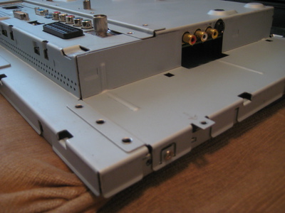
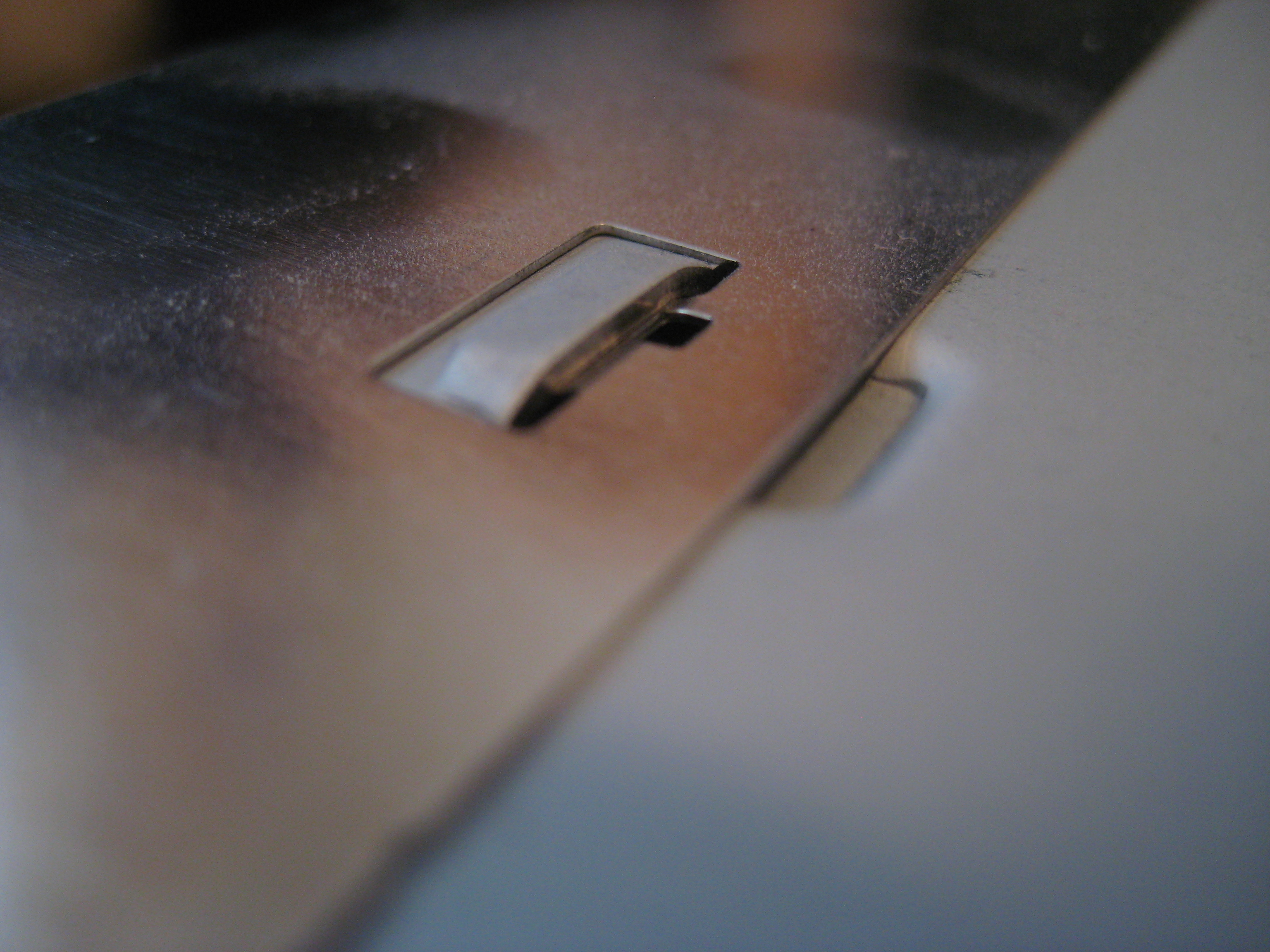
First, note that the back panel has the following to say about this endeavor:
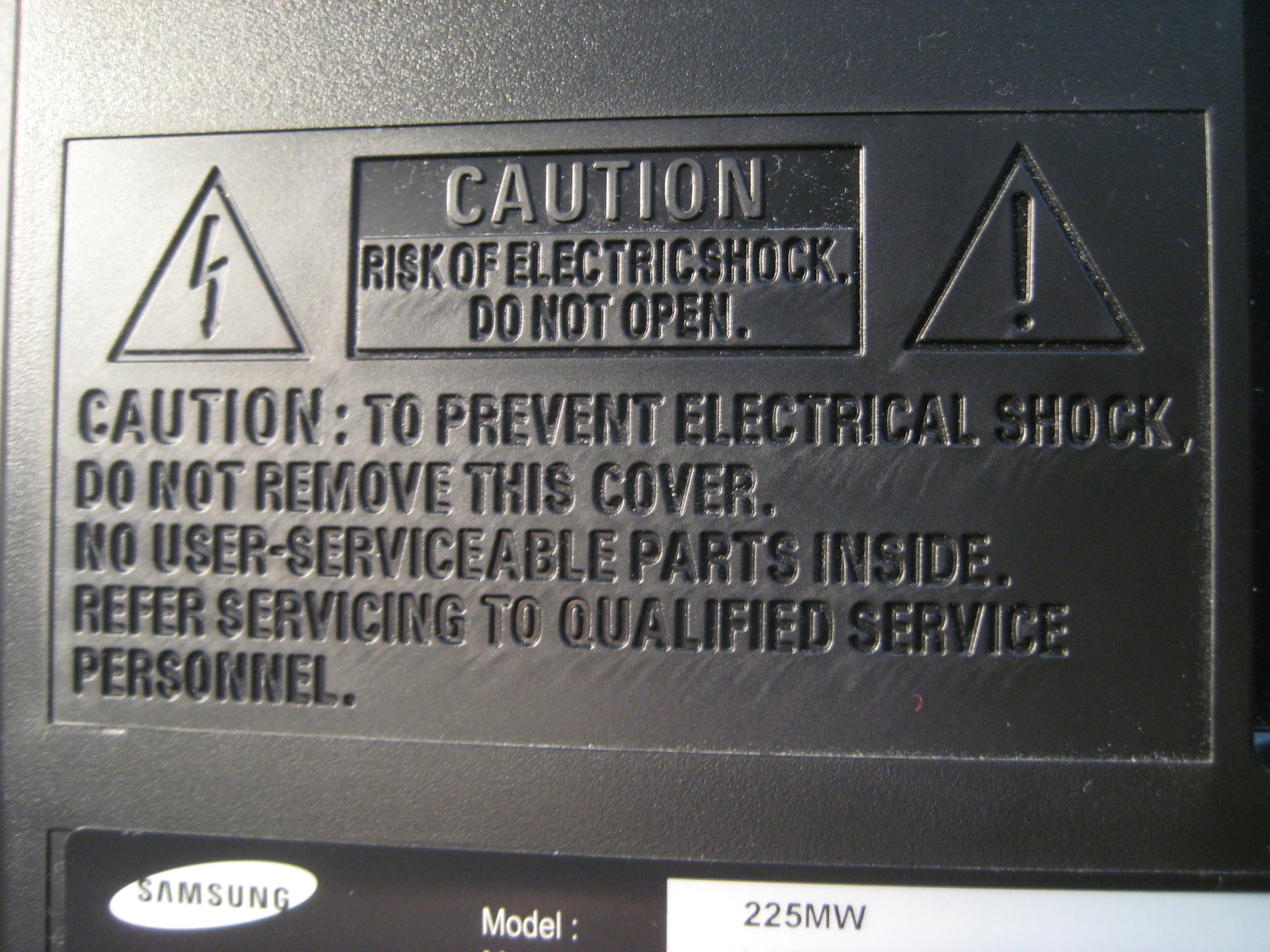
Read it and ponder. Personally, I removed the cover and continued. Choose your destiny. Capacitors can retain voltage for several days after unplugging the system. You can discharge them by probing them with a voltmeter, which has the advantage of showing you the progress in decreasing voltage.
I also do not use the original table stand, so if you do, removal of that should be prefixed to the below algorithm. It should be self-explanatory to remove: four clearly marked screws in the back.
Put the monitor face-down on a gentle surface and let the project begin.
The back panel had two clearly marked screws along the bottom edge. Remove those.
The black polished frame that faces forward and surrounds the panel is attached with clips on the left, right and upper edge.
Use the flat jeweller's screwdriver and drag it along the edge from the bottom and up. When it gets stuck, bend the front plastic frame outwards until the clip detaches with a "snap".
There are three clips on each side. When only the top clips remain, lever the frame forward until they have no other option than to peacefully let go.
This is the first sight that meets you. This picture is also the main reference in steps 4 through 6.
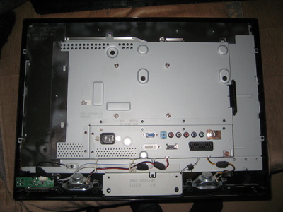
Disconnect the speakers and the front panel. The cables are clipped on to the inner circuit board and need more technique than force.
Remove the metal shielding seen to the left in the reference picture. It is not fastened with any screws — just the slide-in sockets in the metal casing.

Gently bend the leftmost part of the shielding and it should easily come off.
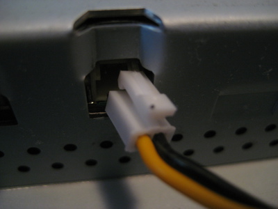
Beneath the removed shielding, four more cables are to be removed.
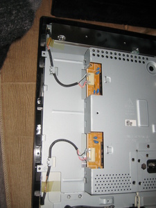
Cut the tape that fixes the cables to the chassi.
Note that these cables provide the power for the backlight. Also note the cable order: the light-blue cable is on top of the red one at both connectors.
Remove the single screw that creates the ground connection between the front panel and the metal casing, and five screws (two to the left, two to the right and one at the bottom) marked with arrows that secure the front panel to the metal casing. Also remove the plastic guide to the composite video signal input on the right side of the metal casing (it is not even fastened by a screw). Now the entire metal casing should be able to be lifted freely from the plastic frame.
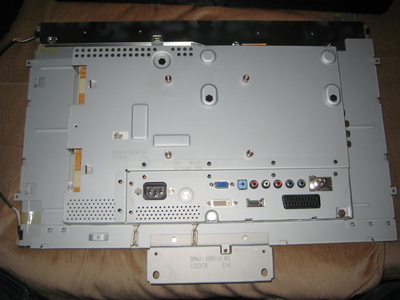
Remove the four smaller screws that attach the LCD panel to the metal casing. One is blurrily shown in the lower part of the below image.
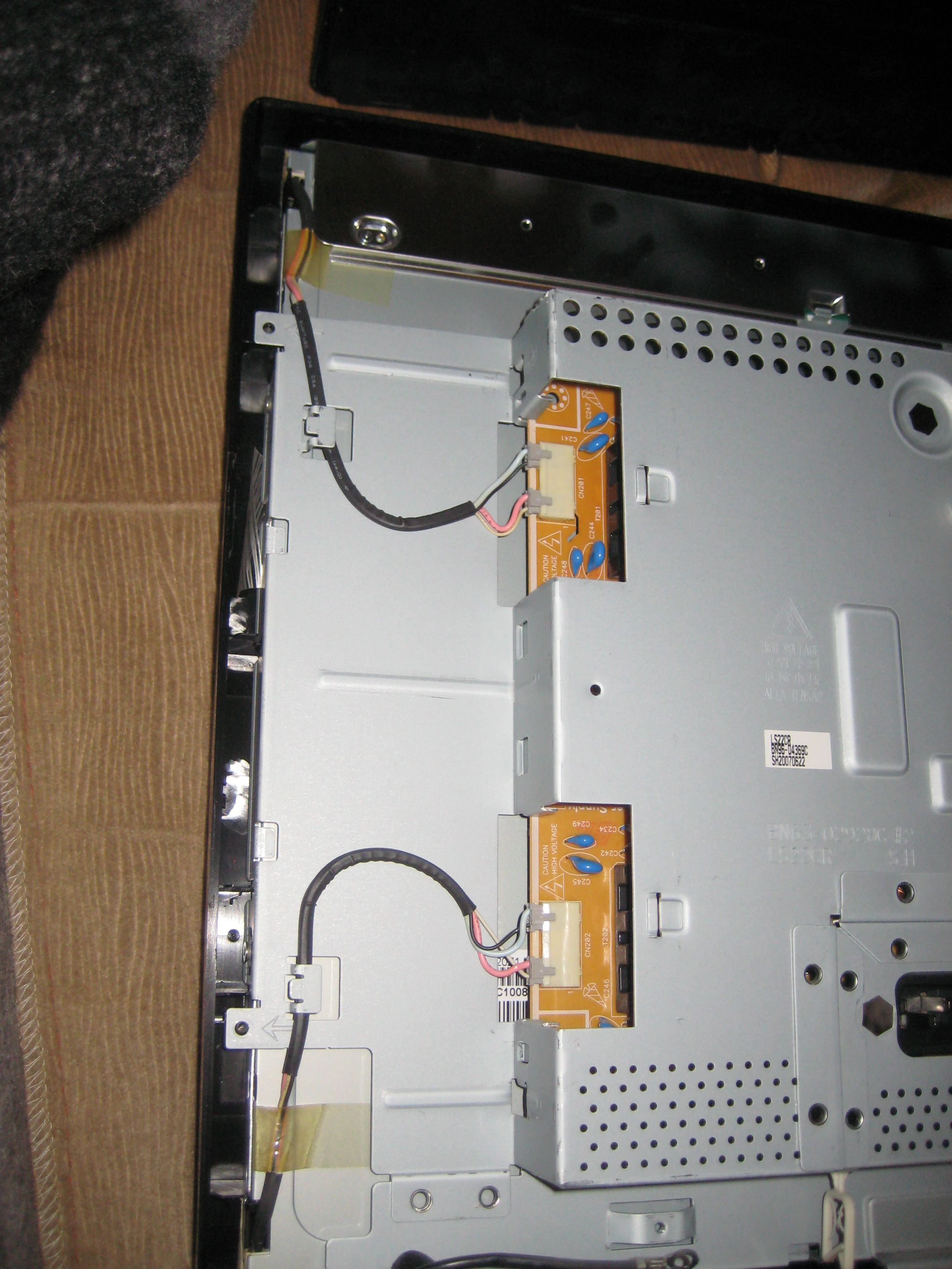
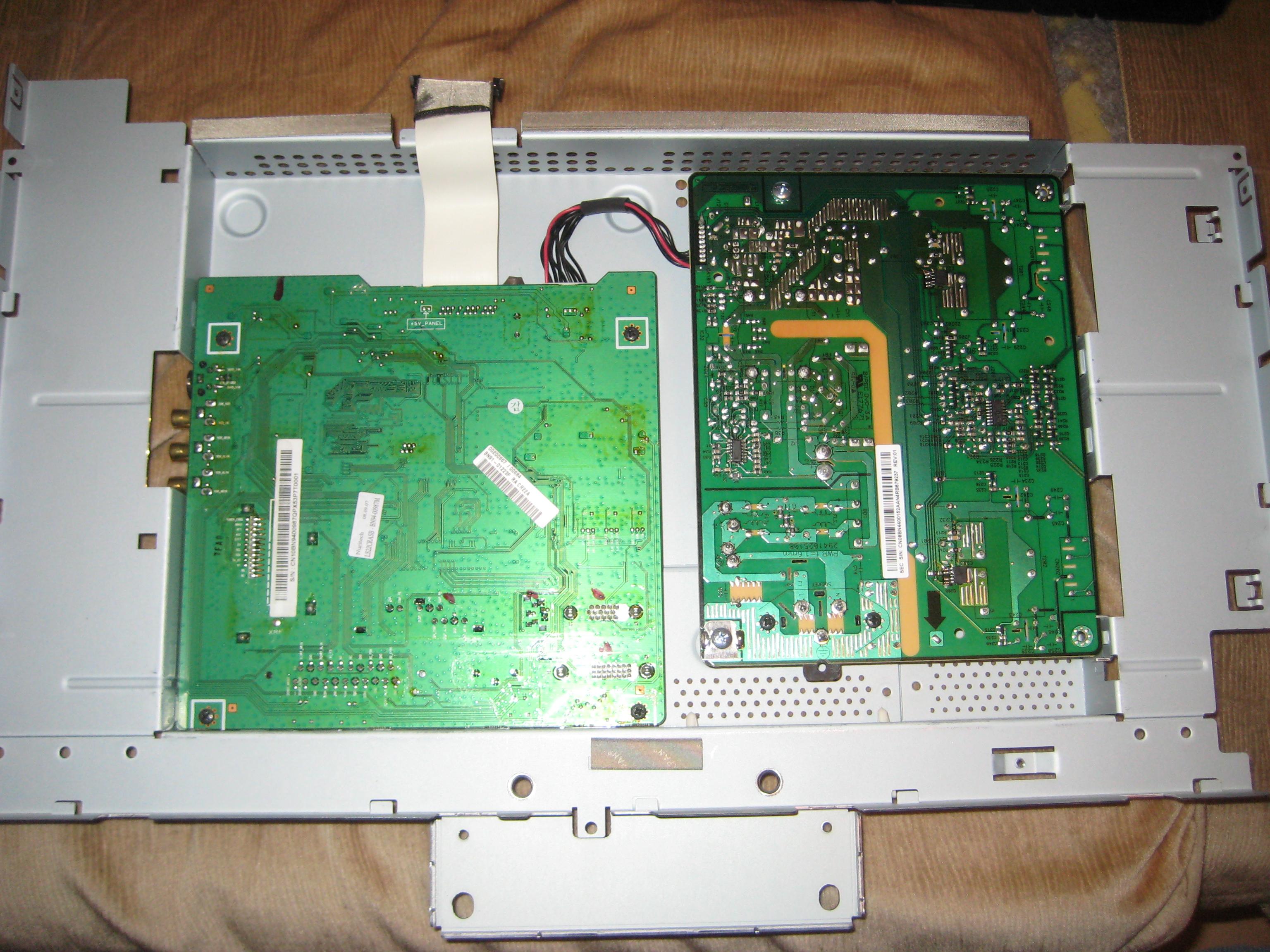
The LCD panel can now be hoisted, but a ribbon cable at the top of the panel connects it to a circuit board underneath. There is some room to play with, although not much. Carefully angle the metal chassis upwards around its upper edge as shown in the picture below and remove the ribbon cable attached to the panel.
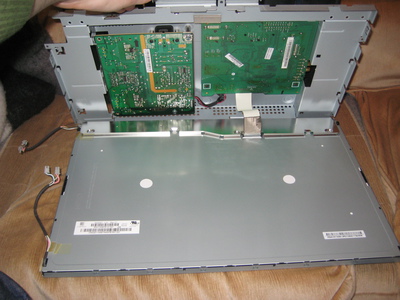
The right circuit board in the picture below is the power supply and the goal of this disassembly.

Detach the cable connecting it to the connector board. Remove the four screws holding it to the metal casing (two larger grounding screws and two smaller black screws) and lift it out. Note that there are two small slots in the metal casing that needs to be aligned with the board for reassembly.
This is where my notices before point 1 in this tutorial and the "High voltage" warning on the back panel starts coming in to play. The capacitors can hold voltage enough for injury, in particular the largest one. If you feel uneasy, read up on the subject or ask someone with experience.


The disassembly is complete. Onwards to the components!
Capacitor inspection and ordering
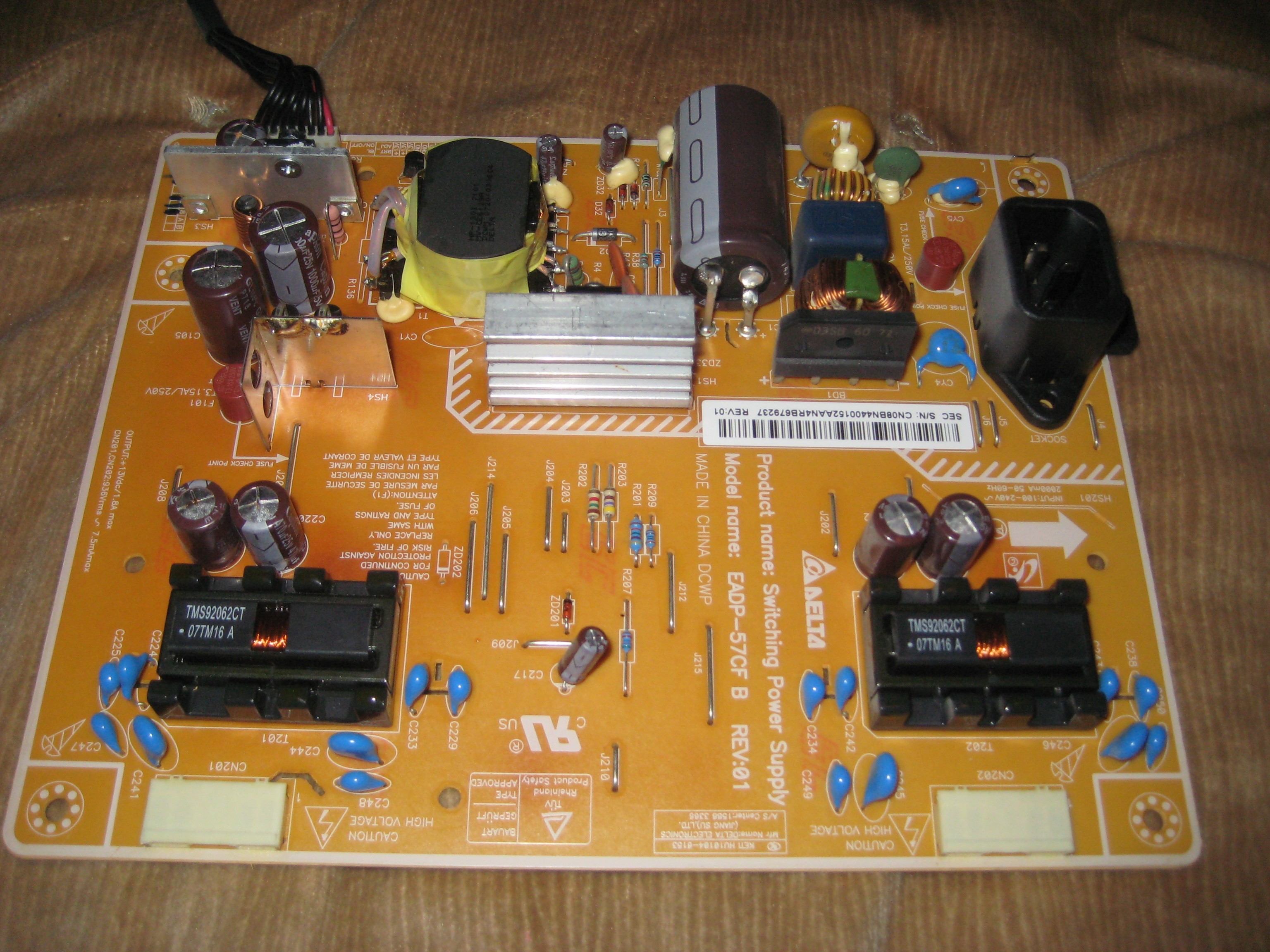
The usual suspects are the four identical capacitors located symmetrically in pairs of two at the left and right edge of the board. They provide the power for the backlight. A capacitor in bad condition is indicated by a bulge at the top, and perhaps a leak of a brownish liquid (dielectric fluid). In my case, the five mid-sized (one hides in the upper left corner behind a shield) and one of the two semi-large capacitors are seen to be in exactly such bad shape and I opted for changing them all at once.
Note the values on the larger one:
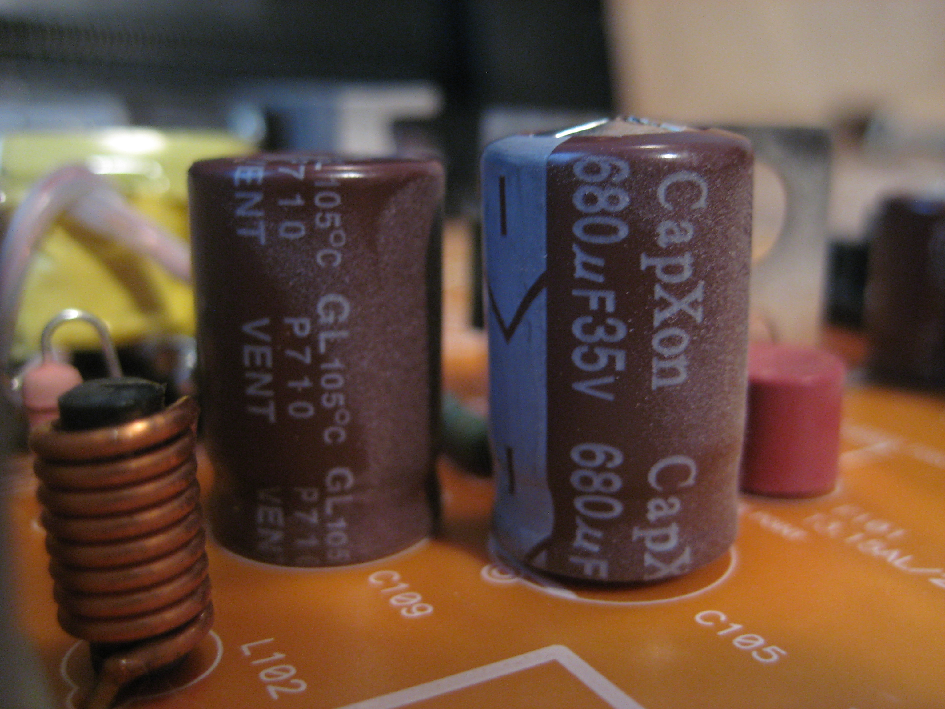
and the mid-sized ones:
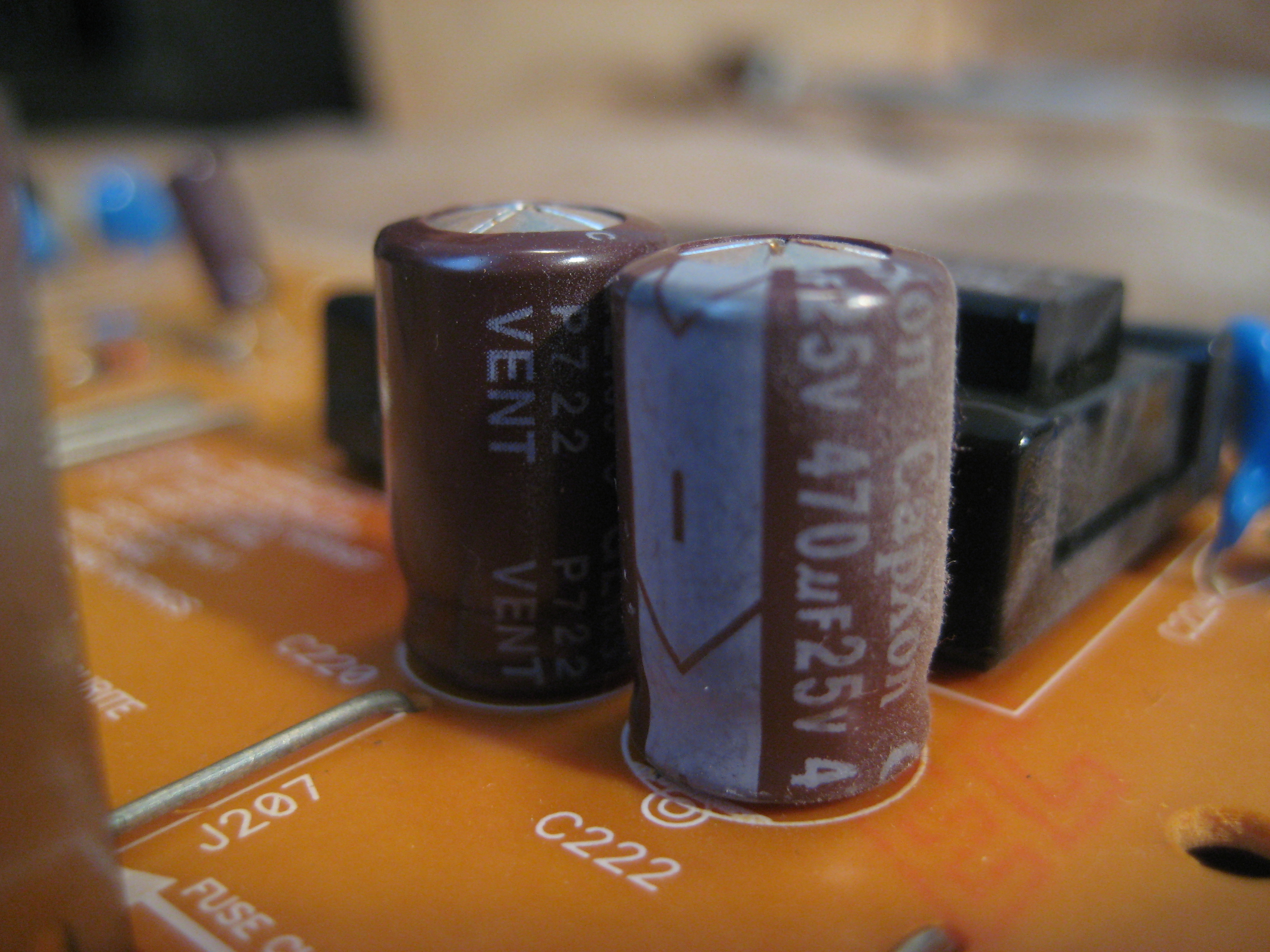
In my case the larger one has capacitance value 680 µF and voltage rating 35 V, and the smaller ones are at 470 µF and 25 V, all at a temperature rating of 105 °C. Note these values when looking for replacements.
My local electronics dealer was ELFA. The components I was looking for were located at
- Passive Components
- → Capacitors
- → Electrolytic Capacitors
- → Aluminium Electrolytic Capacitors with Radial Connections
Capacitors cost more or less nothing, so I suggest indulging yourself with one of the more high-end (== more expensive) manufacturers. Japanese components (Suncon, Rubycon, Panasonic, etc.) are generally considered to be of high quality. I spent a total of 17:21 SEK on five of the mid-sized and two of the semi-large ones; about the price of 2 l of milk (I had full discount at this retailer though. In any case it will be an irrelevant amount of money as compared to a new monitor).
You want capacitors that are noted as "Low impedance" or "Low Equivalent Series Resistance (ESR)" or "Low internal resistance" or something like that (all equivalent). The more expensive items rated at high temperatures (at least 105 °C as mentioned in this case) are most likely of this type.
Also note the physical dimensions of your components. Actually, the semi-large ones I ordered were out of stock and got replaced by a significantly larger item, but by bending the capacitor legs at a right angle it worked out anyway.
If you are cheap and get bad components, chances are that you will have to do all this again in a month or so.
If you cannot find the exact ratings of your capacitors at your dealer, you can go up in the voltage rating without trouble (it just denotes a maximum threshold) but avoid deviating from the capacitance rating much, if at all.

They have arrived!
Capacitor switch

If you are unfamiliar with soldering, chances are you do not have soldering equipment available either. Ask someone more experienced to help you, or see it as a (possibly expensive) learning lesson. This is not a guide on soldering technique, so I will not go into this step in detail.
A quick remark, since it is fundamental: note the polarity (+/‒) of the capacitors and make sure you mount the new ones back in the same orientation. Otherwise they will most certainly break down and rapidly, quite frankly, explode.
Another thing worth to mention is that the components were particularly reluctant to desoldering, for some reason. Temperatures of 350–400 °C were needed to loosen the joints.

The final result. Note the angled mounting of the right-most capacitor I mentioned earlier.
Reassemble
Like the disassembly, but backwards.
Did it work?
Great!
Did it not work?
Too bad.
If you want to spend more time on it: check the soldered joints for shorts, and if you have the equipment you could check the capacitance values of the components, but they are not likely to deviate from their markings.
You can also find complete power supply boards for about $25 on e.g. a certain large internet auction site. Search for the board model number (EADP-57CF in my case) and you will most probably find several sellers.
But where is the fun in that?